General Information
Disc Spring Characteristics
Calculated Characteristic vs Actual Test Results
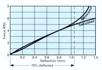
The example illustrated above is typical of most disc springs, and underlines the necessity of limiting maximum deflection to 75% to avoid sharply increasing force and stress characteristics.
As the compressed disc spring nears its ‘flattened’ condition, the reducing cone angle results in the movement of bearing point toward the centre, thus effectively shortening the ‘lever’ length and ‘stiffening’ the spring.
Examples of varying Cone Height / Thickness Ratios
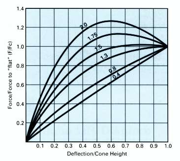
The ability to change the force/deflection characteristic, by way of varying the cone height to thickness ratio, is a particularly useful feature of the disc spring.
Shown above are some examples of different cone height to thickness ratios, and up to a ratio of 1.5 the disc springs may safely be taken to ‘flat’ or stacked in columns.
Above ratio 1.5 the disc spring will adopt a regressive characteristic, and is capable of ‘push-thro.’ if not fully supported. Disc springs with cone height/thickness ratios above 2.0 may invert when compressed toward the ‘flat’ condition.
Disc Spring Nomenclature
| Symbol | Unit | Description |
|---|---|---|
| De | mm | Outside Diameter |
| Di | mm | Inside Diameter |
| t | mm | Thickness |
| ho | mm | Cone Height |
| lo | mm | Overall Height |
| s | mm | Deflection |
| F | N | Spring Force (at deflection s) |
| Fc | N | Spring Force (at s = ho) |
| E | n/mm | Modulus of Elasticity |
| m | – | Poisson’s Ratio |
| i | – | No. of alternating discs (or clusters) in stacked column |
| n | – | No. of discs arranged in parallel (“nested”) |
| t’ | mm | Reduced Thickness – With bearing flats |
| h’o | mm | Increased cone height – With bearing flats |
Disc Spring Selection
- If the application involves large numbers of deflection cycles, i.e. ‘dynamic’ application, or if the required forces or deflections are of a critical nature, we strongly recommend that you select from the range of disc springs that conform to the DIN 2093 specification.
- From the range available, select the largest possible disc spring compatible with the desired characteristics. This will assist in maintaining the lowest possible stresses, thus enhancing the fatigue life, and in the case of stacked columns the greater deflection offered by the larger diameter springs will ensure the shortest possible stack length.
- For static, or dynamic applications, select a disc spring that at 75% of its total available deflection offers the maximum force and/or deflection required. Between 75% deflected and the ‘flattened’ position, the actual force/stress characteristics become considerably greater than those calculated.
- As a result of manufacturing processes, residual tensile stresses occur at d , the upper inside diameter edge, which will revert to normal compressive stresses when the disc spring is deflected by up to approximately 15% of its total deflection.
The fatigue life in applications involving large numbers of cyclic deflections, will be drastically reduced by these stress reversals. For this reason alone, it is important that disc springs used in dynamic applications are pre-loaded to a minimum of 15% of their total available deflection.
Disc Spring Installation
Guidance and Location
Proper guidance and location of disc springs is essential to their performance, and will ensure that the desired characteristics and repeatability is achieved.
Recommended guide clearances are shown in the tolerance tables, and it is also necessary to pay some attention to the nature of the guidance and seating surfaces.
Much depends upon the severity of duty in the application, e.g. if the disc is to be used as a means of providing a static clamping force on ‘mild steel’ or cast/forged steel surfaces, this is probably satisfactory. However, if the seating faces are in aluminium, copper, brass etc; then it is preferable to provide a hardened thrust washer to alleviate face damage/indentation. Dynamic applications, involving large numbers of deflection cycles, will require that in addition to hardened seating faces the guidance surfaces must also be sufficiently hard to prevent excessive wear or ‘stepping’. For both support washers and guide elements, a polished surface with hardness of 58HRC is sufficient, and case depth should be 0.60mm min. Nitride hardening is permissible, providing that the hardened surface layer is adequately supported.
Extending Life with Lubrication
A most important aid to efficient and extended life of disc springs is the provision of some form of lubrication. For relatively low-duty disc spring applications, i.e. small numbers of deflection cycles, a liberal application of suitable solid lubricant, (e.g. molybdenum-disulphide grease), to the contact points and locating surfaces of the spring, is adequate.
For more severe applications of a dynamic or highly corrosive nature, the disc springs will benefit from maintained lubrication, and are often housed in an oil or grease filled chamber.
Disc Spring Materials
Materials: Standard Range
| Material | Ck 75 | 50 Cr V4 | X12CrNI 177 | X7CrNIAl 177 | X35CrMo17 | X22CrMoV 121 | |
|---|---|---|---|---|---|---|---|
| DIN ref. no. | 1.1248 | 1.8159 | 1.4310 | 1.4568 | 1.4122 | 1.4923 | |
| Carbon (C) | 0.7-0.8 | 0.47-0.55 | ≤0.12 | ≤0.09 | 0.35 | 0.2 | |
| Silicon (Si) | 0.15-0.35 | 0.15-0.40 | ≤1.5 | ≤1 | ≤1 | 0.3 | |
| Manganese (Mn) | 0.6-0.8 | 0.7-1.1 | ≤2 | ≤1 | ≤1 | 0.6 | |
| Phosphorus (P) max. | 0.035 | 0.035 | – | – | 0.03 | 0.035 | |
| Sulphur (S) max. | 0.035 | 0.035 | – | – | 0.03 | 0.035 | |
| Aluminium (Al) | – | – | – | 0.75-1.5 | – | – | |
| Chrome (Cr) | – | 0.9-1.2 | 16-18 | 16-18 | 16.5 | 12 | |
| Nickel (Ni) | – | – | 6-9 | 6.5-7.75 | – | 0.6 | |
| Vanadium (V) | – | 0.1-0.2 | – | – | – | 0.3 | |
| Molybdenum (Mo) | – | – | – | – | 1.15 | 1 | |
| E Mod. (N/mm2) | 206,000 | 206,000 | 190,000 | 195,000 | 206,000 | 206,000 | |
| Temperature °C | -10/ +100 |
-40/ +200 |
-200/ +200 |
-200/ +200 |
-40/ +350 |
-40/ +450 |
|
Materials: Specialised Applications
| Material | Inconel X750 | Inconel 718 | Nimonic 90 | A286 Alloy | FV520B | CuBe2 | |
|---|---|---|---|---|---|---|---|
| DIN ref. no. | – | 2.4668 | 2.4969 | 1.4980 | – | 2.1247 | |
| Carbon (C) | ≤0.08 | ≤0.08 | 0.09 | ≤0.08 | 0.048 | – | |
| Silicon (Si) | ≤0.5 | 0.35 | ≤1 | 1 | 0.37 | – | |
| Manganese (Mn) | ≤1 | 0.35 | ≤1 | 2 | 1.05 | – | |
| Phosphorus (P) max. | – | 0.015 | – | – | 0.020 | – | |
| Sulphur (S) max. | 0.01 | 0.015 | 0.015 | – | 0.014 | – | |
| Aluminium (Al) | 0.4-1 | 0.2-0.8 | 1-2 | 0.35 | – | – | |
| Chrome (Cr) | 14-17 | 17-21 | 18-21 | 13.5-16 | 16-18 | – | |
| Nickel (Ni) | ≤70 | 50-55 | Rest | 24-27 | 5.47 | +Co=0.2-0.6 | |
| Vanadium (V) | – | – | – | 0.1-0.5 | – | – | |
| Molybdenum (Mo) | – | 2.8-3.3 | – | 1-1.75 | 1.72 | – | |
| Tungsten (W) | – | – | – | – | – | – | |
| Titanium (Ti) | 2.25-2.75 | 0.65-1.15 | 2-3 | 1.9-2.3 | 0.10 | – | |
| Beryllium (Be) | – | – | – | – | – | 1.95 | |
| Copper (Cu) | 0.5 | 0.3 | 0.2 | – | 2.08 | Rest | |
| Cobalt (Co) | – | 1 | 15-21 | – | – | – | |
| Iron (Fe) | 5-9 | – | 2 | – | – | – | |
| Niobium (Nb) | 0.95 | – | – | – | – | – | |
| E Mod. (N/mm2) | 214,000 | 208,000 | 220,000 | 199,000 | 210,000 | 135,000 | |
| Temperature °C | -200/ +500 |
-200/ +400 |
-200/ +600 |
-200/ +700 |
-90/ +300 |
-250/ +150 |
|
Protective Surface Treatments
Introduction to Protective Surface Treatments of Disc Springs
Obviously, the choice of available types of surface treatments is almost endless, therefore we think it sufficient to discuss only those treatments that currently are most commonly applied to disc springs. However, with consideration to ‘plating’ treatments, it is absolutely essential to bear in mind the following:-
DO NOT ELECTROPLATE DISC SPRINGS
During the process of electroplating, hydrogen gas may be absorbed through the surfaces of the disc spring, which in turn may lead to the spring becoming brittle. Whilst it is possible that a subsequent heat treatment, referred to as de-embrittle may relieve this condition, our experience has shown this to be unreliable.
Phosphating
A zinc phosphate coating usually with subsequent oil or wax treatment. This treatment is widely offered as ‘standard’ on most stock-range carbon steel disc springs. The protection offered is sufficient to prevent corrosion throughout storage and normal transit conditions. It is adequate also for those applications where the disc springs are not directly exposed to the elements. However, where the application involves a more hostile environment, i.e. disc springs open to weather or marine conditions, chemical or acid laden atmosphere, etc; then a superior treatment or material must be considered.
Mechanical Zinc Plating
This is a method of depositing substantial thicknesses of zinc on the surfaces of disc springs without the risk of ‘hydrogen embrittlement’ associated with normal electro-plating. The zinc is impacted onto the surfaces by way of tumbling the disc springs in a rotating barrel, together with glass beads, metal powder, and promoting chemicals. In addition to removing the risk of embrittlement, the ‘peening’ aspect of this process is beneficial in terms of some stress relieving of the components. There are two forms of subsequent passivation treatment:-
- Clear Passivation – Prevents oxidation of zinc coating in storage, handling, and transit. It also assists in maintaining the aesthetic appearance of the zinc plate.
- Yellow Chromate Passivation – The advantages are similar to those described for clear passivation, with the additional benefit of slightly enhanced corrosion resistance. The only disadvantage is that the ‘gold’ tint is often of a patchy ‘non-uniform’ nature and may prove unacceptable if appearance is critical.
Electroless Nickel (Kanigen) Plating
As is the case with mechanical plating processes, the risk of hydrogen embrittlement is avoided with this method of chemically depositing a nickel coating. However, compared with other treatments discussed here, this process is relatively costly, but the high degree of corrosion resistance and smooth ‘satin-like’ finish often justify the extra expense.
Sheradizing
The sherardizing process again uses zinc, this time in the form of zinc dust mixed with an inert filler which, together with the parts to be coated, is placed in a sealed container. The container is placed in a special furnace and rotated at a temperature which is sufficient to ‘fuse’ the coating but without risk of affecting the spring properties of the components. Coating thicknesses from 10 micro metres to 50 micro metres are possible, which makes for a wide range of protective coatings.
Delta – Tone
This process involves dipping the components in an organic resin and zinc mixture, the surplus is removed by spinning, and the bonding of the coating is completed at oven temperatures which have no effect on the metallurgical or heat treatment properties of the components. Salt-spray corrosion resistance tests on this coating can result in a performance equivalent to that obtained with electroless nickel plating.
Helpful Stacking Hints
Stacking Diagrams
Single Disc Spring |
Disc Springs in Parellel |
 |
 |
| Total Force = Force of single disc spring Total Deflection = Deflection of single disc spring |
Total Force = 2 X Force of single disc spring Total Deflection = Deflection of single disc spring |
Disc Springs in Series |
Disc Springs in Series & Parellel |
 |
 |
| Total Force = Force of single disc spring Total Deflection = 2 X Deflection of single disc spring |
Total Force = 2 X Force of single disc spring Total Deflection = 2 X Deflection of single disc spring |
Stacking Disc Springs in Series
Single disc springs are assembled ‘opposed to each other’ to form a spring column. This ‘in series’ formation is a means of multiplying the deflection of a single disc spring, the force element remains as that for a single spring.
E.G. A disc spring that requires a force of 5000N to deflect 1mm, when assembled to form a column of 10 disc springs in series, will require a force of 5000N to deflect 10mm.
The cumulative effect of bearing point friction of large numbers of disc springs stacked in series, can result in the disc springs at each end of the stack deflecting more than those in the centre. In extreme cases this may result in over-compression and premature failure of the end springs. A ‘rule of thumb’ is that the length of the stacked disc springs should not exceed a length approximately equal to 3 times the outside diameter of the disc spring.
Normally, disc springs stacked in ‘series’ formation are of identical dimensions, however, it is feasible to stack numbers of disc springs of increasing thickness in order to achieve ‘stepped’ and progressive characteristics. With such arrangements, it is necessary to provide some form of compression limiting device for the ‘lighter’ disc springs, to avoid over-compression whilst the ‘heavier’ springs are still in process of deflection.
Stacking Disc Springs in Parallel
Disc springs are assembled ‘nested’ inside each other, i.e. the same way up, the resultant force for such a column is the force element of a single disc spring multiplied by the number of ‘nested’ disc springs in the column, whilst the deflection remains the same as for that applicable to a single disc spring.
It must be realised that the individual disc springs in a column assembled in parallel perform as separate entities, thus generating considerable interface friction. For a given deflection, this interface friction will result in 3% increased force per interface, this must be taken into account when calculating the total force from parallel stacking.
E.G. A disc spring that requires a force of 5000N to deflect 1mm, when assembled of 3 disc springs in parallel, will require a force of 15900N to deflect 1mm.
It is advised that the number of disc springs in parallel should not normally exceed 3, or in extreme cases 5 springs, to minimise heat generated by friction or, in the case of static applications, to ensure a workable relationship between the loading and unloading characteristics. The hysteresis resulting from parallel stacking can be employed to advantage in those applications of a ‘shock absorbing’ nature, requiring a damping feature.
The life of disc springs in parallel arrangements is very dependant on adequate lubrication of the spring interfaces.
Stacking Disc Springs In Series and Parallel
The combination of both series and parallel stacking is a means of multiplying both force and deflection. The guidelines applicable to this type of arrangement are basically those already outlined, but it cannot be over-emphasised that it is important, at the disc spring selection stage, to minimise the number of springs in the stack by way of examining the various alternatives.
E.G. A disc spring that requires a force of 5000N to deflect 1mm, when assembled to form a column consisting of 3 disc springs in parallel, and 10 units of 3 parallel discs in series – (total 30 discs), will result in a force requirement of 15900N to deflect the stack 10mm – (incorporating an allowance of +6% for friction).